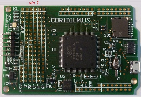
DATA Logger Pin Description
Pins in the Array area
The DATAlogger is the first of the multi-core CPU boards from Coridium. BASICtools supports multi-core programming .
J1.1 | IO(4) | P1_0 -- SGPIO7 P0_1 -- SGPIO1 P0_0 -- SGPIO0 P1_13 -- SGPIO9 P1_3 --SGPIO10 P1_15 -- SGPIO2 P1_4 -- SGPIO11 P1_5 -- SGPIO15 P9_6 -- SGPIO8 P9_5 -- SGPIO3 P6_6 -- SGPIO5 P6_7 -- SGPIO6 P2_3 -- SGPIO12 P2_4 -- SGPIO13 P2_5 -- SGPIO14 P7_0 -- SGPIO4 WAKEUP PF_4 -- CLKIN |
J2.1 | IO(8) | P1_1 -- pulled up during RESET
(required for correct boot) P1_2 -- pulled down during RESET (required for correct boot) CLK0 P1_10 P1_14 P4_9 .. P1_6 .. P6_2 P2_7 -- pulled up during RESET (required for correct boot) -- connected to LED and ISP BOOT pin P2_8 -- pulled down during RESET (required for correct boot) P6_10 P2_10 P4_6 P3_0 .. RTC_ALARM |
J3.1 | IO(174) | P4_10 P1_9 P1_12 P5_2 P5_7 P1_18 P6_1 P2_0 P2_1 P4_7 I2C0C P6_9 P2_9 -- pulled down during RESET (required for correct boot) P2_12 P7_1 P7_3 P4_2 RESETn |
J4.1 | IO(73) | P5_0 P1_8 P1_11 P5_4 P1_16 P1_19 P6_0 P6_4 P2_2 P4_8 USB1P I2C0D P6_11 P2_11 P3_1 P7_2 P4_4 P7_6 |
J5.1 | IO(74) | P5_1 P1_7 P5_3 P5_5 P5_6 P1_17 P1_20 P6_3 P6_5 P6_8 USB1M P2_6 CLK2 P6_12 P2_13 P3_2 P4_0 P4_5 |
Alternate Pin functions
The LPC4330 supports a number of dedicated functions. Those include 4 UARTs, USB, 2 SSPs, 1 SPI, 2 CAN, 2 I2C, I2S, 2 multi-channel PWMs, Quadrature Encoder, dedicated motor control PWM, interrupts, timer counter capture and match.
In addition most can be configured with pull-ups and default to pull-ups following reset.
Details can be found in NXP's User manual.
UARTs are enabled by calling BAUD(x) for x=0 to 3. UART0 is enabled by default as the programming debug connection. The pin assignment BASIC uses is in the following table (you can change the settings by changing the PINSEL registers, details in the NXP User Manual)
| UART | BASIC | NXP | UART |
| RXD(0) | IO(161) | P2_1 | UART0 |
| TXD(0) | IO(160) | P2_0 | |
| RXD(1) | IO(39) | P1_14 | UART1 |
| TXD(1) | IO(38) | P1_13 | |
| RXD(2) | IO(3) | P1_16 | UART2 |
| TXD(2) | IO(2) | P1_15 | |
| RXD(3) | IO(164) | P2_4 | UART3 |
| TXD(3) | IO(163) | P2_3 |
Power connections
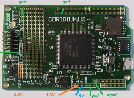
Diode steering allows 5V power to be supplied from either the USB connector or the 6 pin Serial Debug connector.
If you intend to supply 5V power from the Arduino 6 pin power connector, you should not connect the USB connector.
The schematic describes this circuit
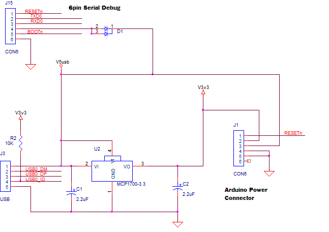
The full schematic can be seen here
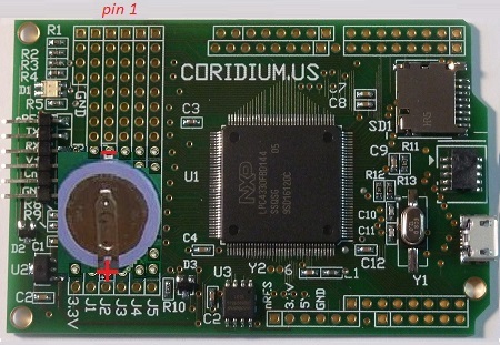
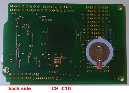
Real Time Clock Oscillator
The DATAlogger has a provision to load a 32 KHz crystal (Y2) and 2 20pf caps (C9 and C10) to use that for the Real Time Clock. It can also add battery backup by loading the ML2020 battery (on either top or bottom of board), 330 ohm resistor (R5) and a BAT54C diode (D3).
The crystal should be a 32.768 KHz can type with an 18pF rating the capacitors are 0603 size 20pF.
 ..
..
To startup a user BASIC program when a battery is installed add this code to the start of your code
#include "LPC43xx.bas"
main:
RTC_REGFILE(63) = 0 ' you can also use other values to indicate other features to control your program.
The firmware writes either &H41BEAAAA or &HBE415555 which if found on startup inhibits the user program from starting on power up.